Friction and wear testing
Case Study: Reciprocating Sliding Wear Testing
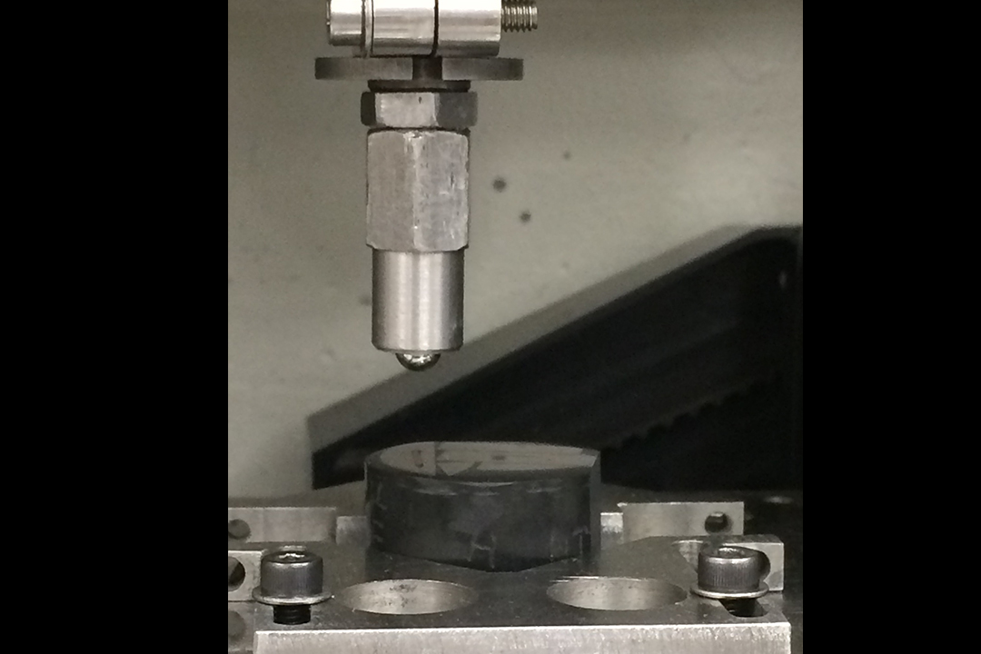
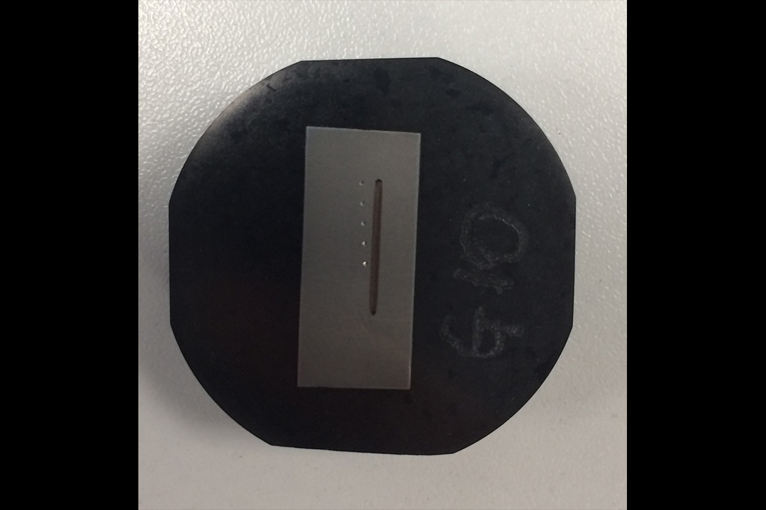
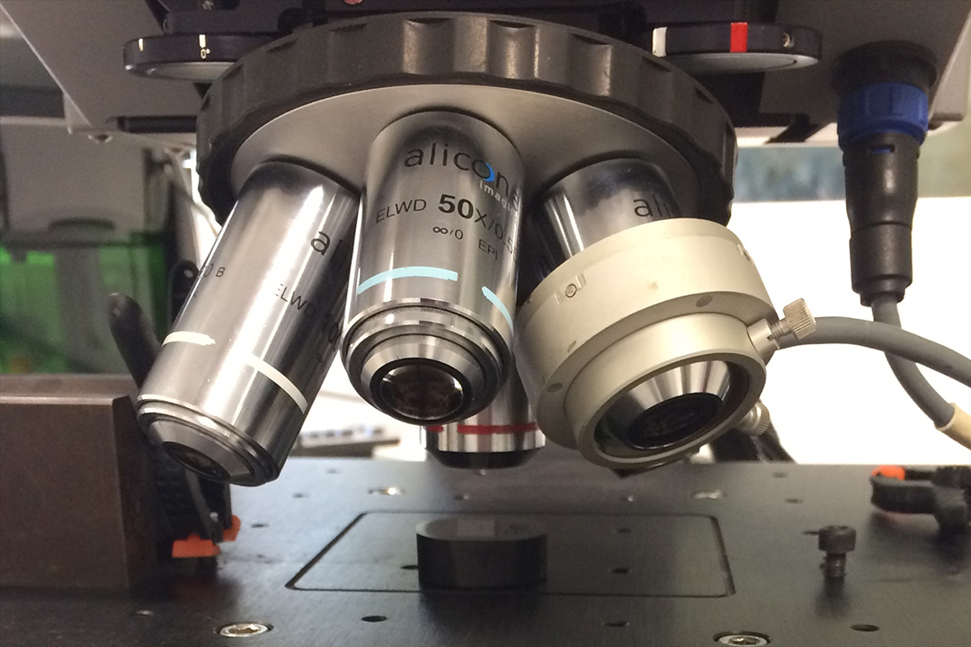
In this instance, two different steel samples, samples G0 and G10, had undergone different heat treatment cycles which could have influenced their wear resistance. The testing setup is shown in Figure 1 and involved using a tungsten carbide pin which is a very hard material and would ensure that all the material that was removed would come solely from the samples. The resultant wear scars, G10's shown in Figure 2, can then be analysed on an Infinite Focus Microscope (IFM), shown in Figure 3, to determine their depths.
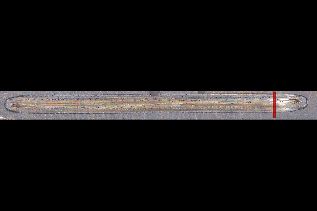
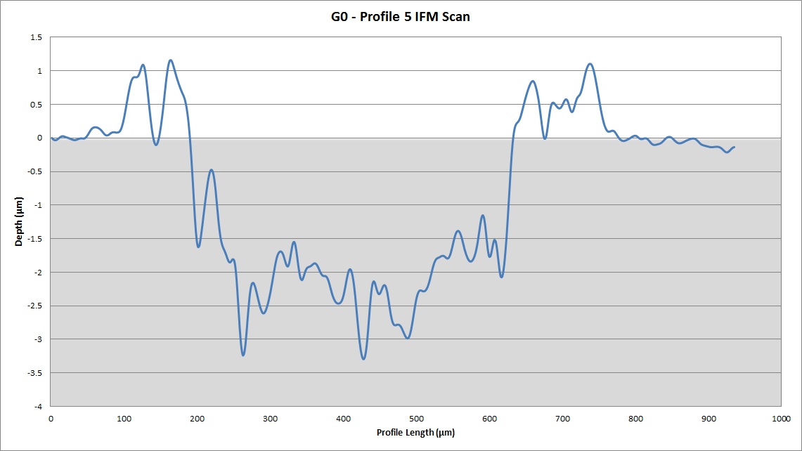
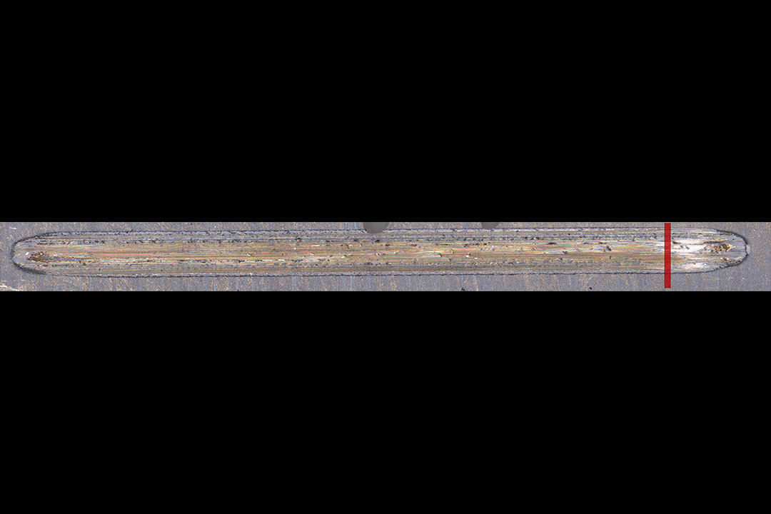
The IFM was used to take five profile measurements for each sample, the average of which would be used to determine the volume loss. The IFM image of the wear scar from sample G0 is shown in Figure 4 along with the location of the fifth profile measurement, the result for which is shown in Figure 5.
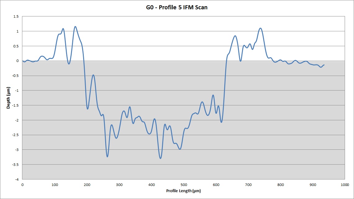
Figure 5: Profile 5 of the Wear Scar on Sample G0
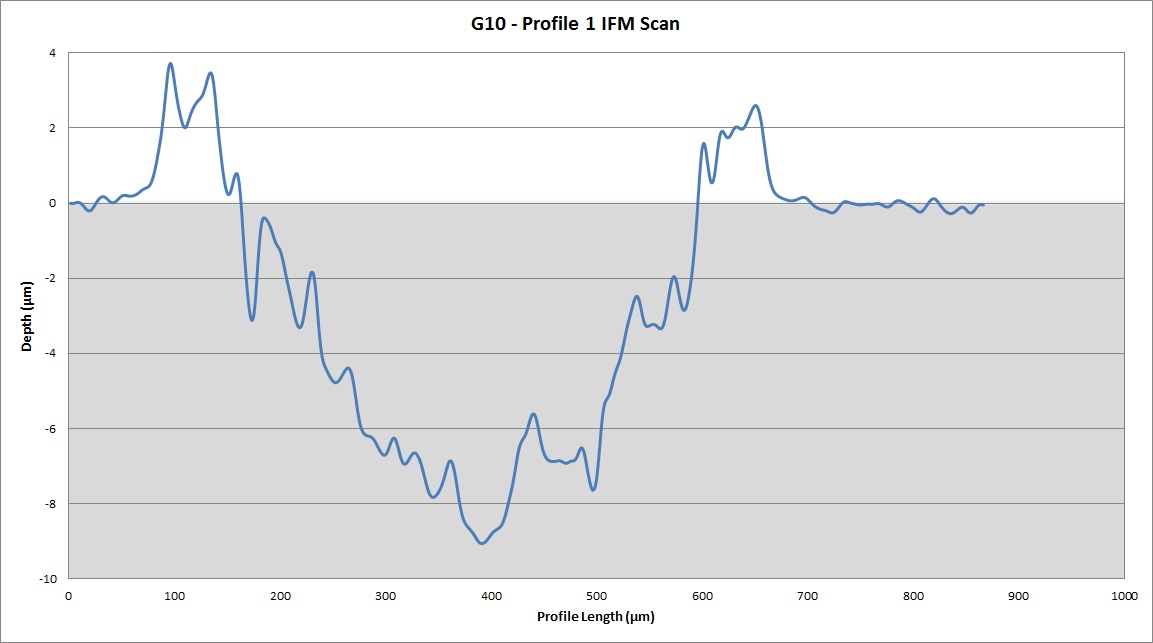
Additionally, the IFM image of sample G10 is shown in Figure 6 along with the location of the first profile measurement, the result for which is in Figure 7.
Both profile scans demonstrate the "bathtub" effect on the sides of the wear scar where material has built up due to plastic deformation as the wear testing progressed.
The volume loss is determined by taking the average cross-sectional area of the five profile scans beneath the zero point of the sample surface, indicated by the shaded grey area, and multiplying this by the wear scar length (10mm).
In this particular example, this resulted in a volume loss of 0.0086mm3 for sample G0 and 0.0232mm3 for sample G10 indicating that G0 is the more wear resistant of the two samples by a factor of 2.7 for this particular test.
Additionally, it can be seen that the wear scar for sample G10 is narrower and deeper than G0. This, combined with the different volume losses, shows that different heat treatments of samples can lead to different wear resistance properties.
